#374264 - 03/03/2024 07:44
 Help modding TV - identifying line-level traces?
|
carpal tunnel

Registered: 20/12/1999
Posts: 31634
Loc: Seattle, WA
|
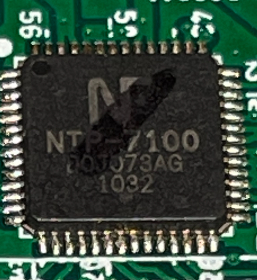
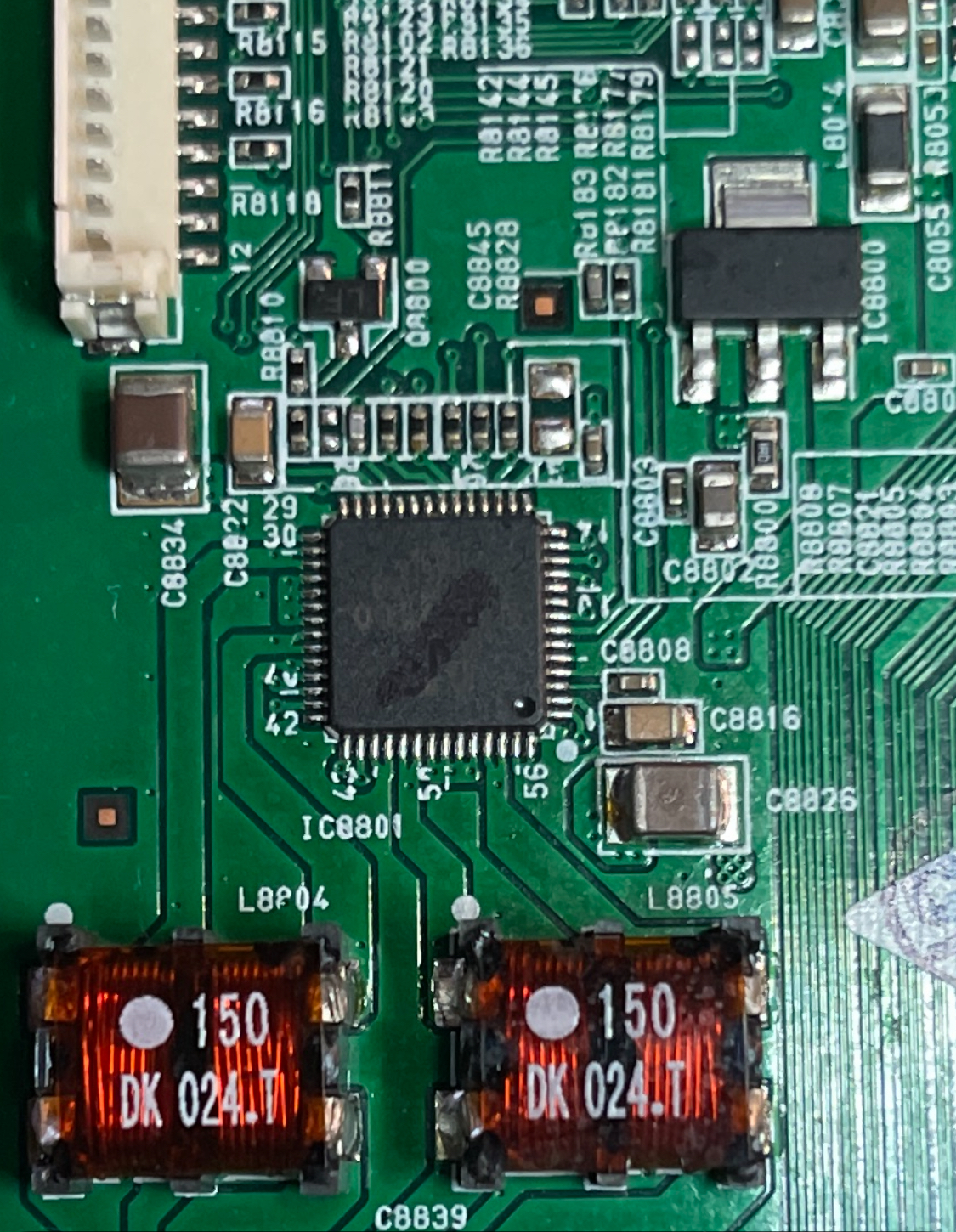
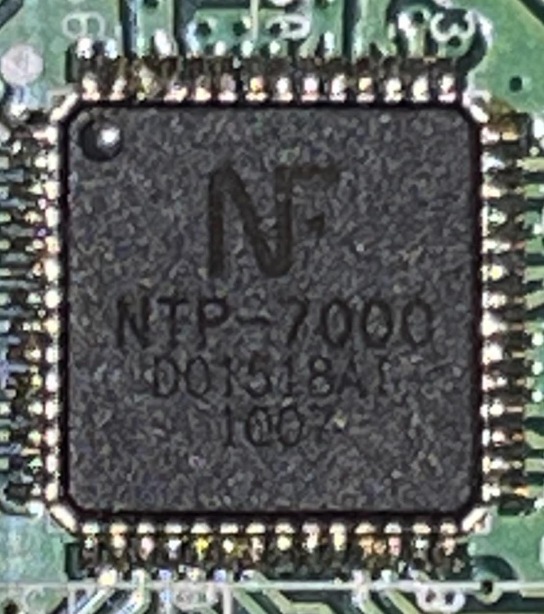
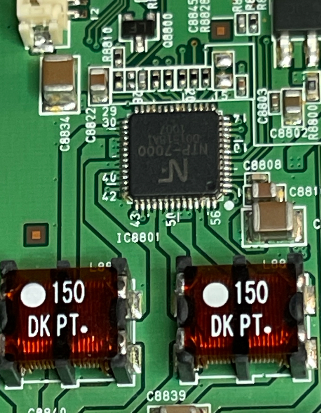
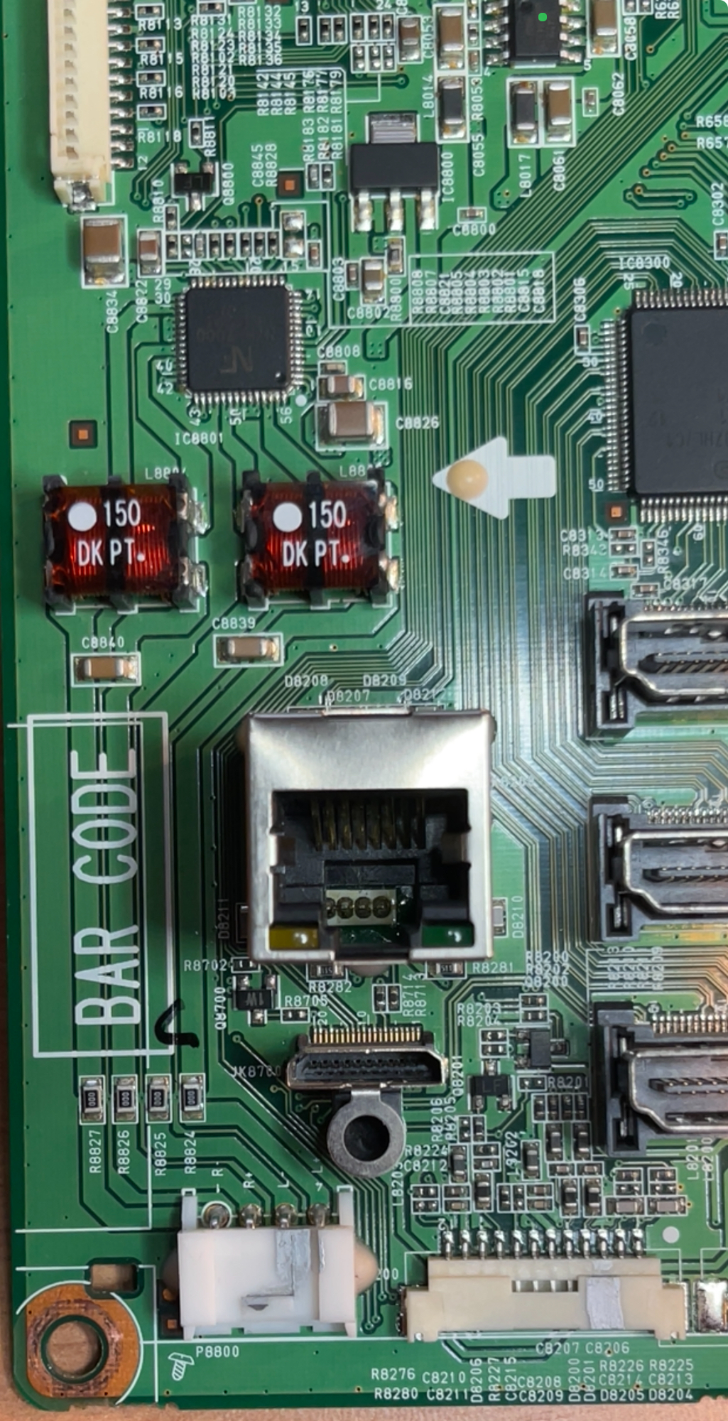
I've got an old television set, an LG model 55LE5400. This TV and I have been through a lot together. I've had to replace its mainboard with ebay parts three times now, because these sets have a well-known tendency for some of their main CPU's BGA pins to work loose after several years of service. The repair method is to either fully reflow and pray, or just buy a known-working mainboard to replace it. The TV has recently had its mainboard replaced, so it's working fine at the moment. I have also recently moved it from being a main living room TV to being a secondary TV that lives in my studio, for gaming and secondary TV watching. It's not *quite* ready to be sent to that farm up north yet. But in its current role, I am thinking I'd like to "mod" the thing to have a line-out for some powered speakers. I'm trying to identify the best place on the board to tap into the line-level audio lines before they hit the TV speaker's amplifier circuit. I'm hoping that the magic of the Empeg BBS can help me find just the right place to tap in. Here's why I want this unusual configuration: - I already have a stereo pair of nice self-powered speakers hooked up to the TV's headphone jack. Actually these speakers are some small near-field studio monitors I had lying around spare, so they sound pretty nice. I'm using one of those adapter cables which turns a 1/8" headphone jack into two RCA cables, and running the RCA outputs to the speakers' line level RCA inputs. This works more or less fine as-is; even though the headphone output isn't really line-level, it's at least low-powered enough not to overdrive those speakers. The TV's remote control is successful at adjusting the volume, and everything works as designed. - I want to keep that basic layout, and keep using that pair of speakers. I don't want to buy any A/V receivers, add any additional remotes, or add any other major new components. I'm aware that my additional issues below would be solved by an A/V receiver, but I have several reasons for not wanting to add that level of complexity at the moment. - My main issue: When something is plugged into the TV's headphone jack, it turns off all of its audio-processing features and grays them out. Through the headphone jack, it delivers pure plain stereo output without any audio processing. It turns out that there's one audio processing feature on the TV that I'd really like to use (called "clear voice II"), but I can't use that in its current configuration, due to this limitation. - I could unplug the headphone jack, forget about the powered speakers, and just use the TV's built-in speakers. This works, it allows all of the audio-processing features to succeed, however, the built-in TV speakers are small and tinny and sound terrible. - I have tried using the TV's fiber-optic cable output, running that to a little Toslink-to-RCA converter box, to drive the powered speakers. This produces sound to the speakers, but, it doesn't solve the problem because it adds two new additional problems: I lose volume control. The volume of the TV's fiber-optic cable output is not controlled by the TV's remote control; the remote still controls the volume of the tinny TV speakers. And if I use the TV's settings menu to turn off the TV speakers, I still can't control the volume of the Toslink output, and ALSO the audio processing features get grayed out again. In fact, I'm not convinced that the audio processing features are even working on the Toslink output at all anyway. So I'm thinking that what I'd like to do is find the line-level part of the audio signal chain on the mainboard, right before it amplifies the sound for the TV's built-in speakers, tap into that, and turn that into a pair of RCA line-outs coming out the back of the TV. I could then unplug the connector to the TV's internal speakers, so that the remote's volume controls only the RCA line-outs and the TV speakers are silent. I believe I've identified the correct section of the mainboard, but I'm having trouble finding the datasheets for the audio amplifier chip and other components, so I don't know the pinouts. I have faith that the folks here would be able to help ID the bits I need to mess with? I have three of these mainboards that I can experiment with at the moment: The primary one is the golden fully functional one, running in the TV right now. The second one is non-functional due to a failed reflow attempt on its main CPU; I could do practice soldering on that board perhaps. The third one is intermittently functional if I push down on the CPU's heatsink; I could use that one for testing that the mod actually works. If it works, then I could implement the final mod on the golden board. All three boards are different revisions, and have slightly different component part numbers, but are basically the same. I'm including photos from the second and third boards so that we can ID the components and their pinouts. Non-functional board: IMG_4886.jpg - NTP-7100 DOJ073AG 1032 - Audio amplifier chip. IMG_4885.jpg - 150 DK 024.T - Possibly audio amplifier transformers? IMG_4884.jpg - Wide shot: Audio amplifier at top, transformers below, connector to TV speakers at bottom. Intermittently-working board: IMG_4887.jpg - NTP-7000 D01518AI 1007 - Audio amplifier chip. IMG_4883.jpg - 150 DK PT. - Possibly audio amplifier transformers? IMG_4882.jpg - Wide shot: Audio amplifier at top, transformers below, connector to TV speakers at bottom. My specific questions: - Can anyone find datasheet or pinouts for the NTP-7000/NTP-7100 audio amplifier chips? I can find the chips by googling but I'm coming up dry in locating their datasheets. - Can anyone find a datasheet or pinouts for those "150 DK" components? Are they audio amp transformers as I suspect? I'm wondering if I merely need to tap some RCA jacks onto their top-right corner pinouts to get the line level I'm looking for? - Any other suggestions?
|
|
Top
|
|
|
|
|
#374265 - 04/03/2024 00:32
Re: Help modding TV - identifying line-level traces?
[Re: tfabris]
|
carpal tunnel
Registered: 20/12/1999
Posts: 31634
Loc: Seattle, WA
|
Aha, the service manual is located here, and it has a separate schematic page for the audio output block. Page 44 of this PDF: https://ia800505.us.archive.org/12/items/LG_55LE5400/LG_55LE5400.pdfSo what's the best spot on that schematic to add a couple of RCA jacks for line-out? I don't comprehend everything that's happening in that schematic. Any ideas?
|
|
Top
|
|
|
|
|
#374266 - 04/03/2024 07:59
Re: Help modding TV - identifying line-level traces?
[Re: tfabris]
|
carpal tunnel
Registered: 20/12/1999
Posts: 31634
Loc: Seattle, WA
|
I tried, just for the heck of it, tapping into the upper pins on those transformers (using my intermittent mainboard). It got output sound to the powered speakers, but it Wasnt line level. It was speaker level and so it was noisy and too loud for the speaker inputs. Disconnected now.
Maybe I should just get a speaker-level-to-line-level converter for this, if I can find one that isnt a car-audio device.
|
|
Top
|
|
|
|
|
#374267 - 04/03/2024 17:00
Re: Help modding TV - identifying line-level traces?
[Re: tfabris]
|
carpal tunnel
Registered: 13/07/2000
Posts: 4182
Loc: Cambridge, England
|
That component appears to be an integrated DAC+amp: I2S in, speaker-level out. It's not clear that there is an exposed line-level signal. A speaker-level-to-line-level converter sounds like it could work.
Peter
|
|
Top
|
|
|
|
|
#374268 - 04/03/2024 20:45
Re: Help modding TV - identifying line-level traces?
[Re: peter]
|
carpal tunnel
Registered: 20/12/1999
Posts: 31634
Loc: Seattle, WA
|
Indeed, I believe you are correct. Hm. All the speaker-to-line converters I can find are for car audio, meaning it would (a) need a 12v power supply back behind the TV and (b) might not be sized correctly for the speaker impedance (though I don't know the impedance of those tiny TV speakers actually). Still, I want to try and figure out something. Maybe something like this would work: https://electronics.stackexchange.com/a/443022I've seen other places on the internet where people described using a simple voltage divider like that, and were unhappy with the results (noisy, etc.). Still, wouldn't hurt to try.
|
|
Top
|
|
|
|
|
#374270 - 10/03/2024 01:14
Re: Help modding TV - identifying line-level traces?
[Re: tfabris]
|
carpal tunnel
Registered: 20/12/1999
Posts: 31634
Loc: Seattle, WA
|
I ended up actually getting one from Crutchfield - I could have wired the same thing myself, but the form factor and ease of connection for that device made it worth grabbing the pre-made version. The result worked, more or less... No noise or hum, but I don't think it attenuated enough. Once I start to push the volume up past the first 8-10 notches from 0, I start to hear some distortion in the signal. Maybe I'll try messing with different resistor values or something.
|
|
Top
|
|
|
|
|
#374271 - 10/03/2024 02:18
Re: Help modding TV - identifying line-level traces?
[Re: tfabris]
|
carpal tunnel

Registered: 29/08/2000
Posts: 14531
Loc: Canada
|
I think resistors will only make a difference when used in pairs, as voltage dividers.
But do a bit of digging and some experiments for sure. You could always join in on the Friday Zoom call and pick Patrick's brain if you haven't solved it by then!
|
|
Top
|
|
|
|
|
#374272 - 10/03/2024 05:40
Re: Help modding TV - identifying line-level traces?
[Re: mlord]
|
carpal tunnel
Registered: 20/12/1999
Posts: 31634
Loc: Seattle, WA
|
Indeed, I believe that the thing that I got was a 2-channel voltage divider. It just doesn't seem to bleed off quite enough of the voltage. So I was thinking of trying to change the value of the resistors in the circuit to quiet it down more. I'll experiment with that maybe tomorrow. The formula for the voltage is pretty straightforward. Plugging the numbers into a calculator, I see that the thing I got, is rigged to make the output voltage about 1/10th of the input voltage. Since that's not enough, I can fiddle with the ratio and try other values. And yeah, I missed my chance to buzz you guys about it on the Friday call. I was busy replacing the kitchen sink faucet that I broke on Thursday. Took me all fscking day because the original faucet's nut was corroded in place and wouldn't come off, in the hard-to-reach spot underneath the counter behind the basins. After enough hours of frustration and twisting and bruising my body, ended up just using a dremel to cut the mofo off of there.
|
|
Top
|
|
|
|
|
#374273 - 10/03/2024 06:29
Re: Help modding TV - identifying line-level traces?
[Re: tfabris]
|
carpal tunnel
Registered: 20/12/1999
Posts: 31634
Loc: Seattle, WA
|
I added some 330ohm 1/4watts in parallel with the 430's already there, making the R2 spot in the voltage divider 186 ohms total, which, in the overall circuit, brings vout down to about 1/20th of vin. The sound is still a bit louder than I'd like, but it's a lot better than it was. I'll probably still experiment more.
|
|
Top
|
|
|
|
|
#374274 - 11/03/2024 10:41
Re: Help modding TV - identifying line-level traces?
[Re: tfabris]
|
pooh-bah
Registered: 27/02/2004
Posts: 1946
Loc: London
|
Indeed, I believe that the thing that I got was a 2-channel voltage divider. It just doesn't seem to bleed off quite enough of the voltage. So I was thinking of trying to change the value of the resistors in the circuit to quiet it down more. I'll experiment with that maybe tomorrow. The formula for the voltage is pretty straightforward. Plugging the numbers into a calculator, I see that the thing I got, is rigged to make the output voltage about 1/10th of the input voltage. Since that's not enough, I can fiddle with the ratio and try other values. And yeah, I missed my chance to buzz you guys about it on the Friday call. I was busy replacing the kitchen sink faucet that I broke on Thursday. Took me all fscking day because the original faucet's nut was corroded in place and wouldn't come off, in the hard-to-reach spot underneath the counter behind the basins. After enough hours of frustration and twisting and bruising my body, ended up just using a dremel to cut the mofo off of there. First use of the f word on the board? 
|
|
Top
|
|
|
|
|
#374275 - 11/03/2024 14:08
Re: Help modding TV - identifying line-level traces?
[Re: tahir]
|
carpal tunnel
Registered: 29/08/2000
Posts: 14531
Loc: Canada
|
First use of the f word on the board? Nope. I do intend to get one of my own done. As an EE it's a fairly simple design On the other hand, if things ever go really *really* bad...and the fuc[b][/b]king intern can't get the arterial line in, give me a call.
|
|
Top
|
|
|
|
|
#374276 - 11/03/2024 15:06
Re: Help modding TV - identifying line-level traces?
[Re: tahir]
|
carpal tunnel
Registered: 20/12/1999
Posts: 31634
Loc: Seattle, WA
|
First use of the f word on the board? What, "faucet"?
|
|
Top
|
|
|
|
|
#374277 - 11/03/2024 16:03
Re: Help modding TV - identifying line-level traces?
[Re: tfabris]
|
carpal tunnel

Registered: 18/01/2000
Posts: 5690
Loc: London, UK
|
I was busy replacing the kitchen sink faucet that I broke on Thursday. Took me all fscking day because the original faucet's nut was corroded in place and wouldn't come off, in the hard-to-reach spot underneath the counter behind the basins. After enough hours of frustration and twisting and bruising my body, ended up just using a dremel to cut the mofo off of there. The wife and I had to deal with one of those a few months back. After the application of multiple rounds of WD-40 over several hours, a tap spanner with a length of pipe attached for extra leverage, and a lot of brute force and ignorance, we finally got it removed.
_________________________
-- roger
|
|
Top
|
|
|
|
|
#374278 - 11/03/2024 16:38
Re: Help modding TV - identifying line-level traces?
[Re: Roger]
|
carpal tunnel
Registered: 20/12/1999
Posts: 31634
Loc: Seattle, WA
|
My sympathies! In hindsight, I would have saved so much time and bruises if I had just gone straight for the dremel. It was very difficult, navigating the tight space under the sink and trying to get leverage in the tiny gap behind the basins. Wasted so much time (hours!) trying to get that nut off of there "nicely" when I had been intending to throw away the old faucet anyway. I called in my roommate Fishy to help me, and after only a couple of tries at the nut, he quickly suggested cutting it off with the dremel. I had to pause and think "oh yeah, I'm not planning to save this old faucet, so that might actually work". Once I'd gotten past that cognitive barrier, the old faucet came off in, literally, seconds.
In other news, I'm having fun experimenting with different resistor values in the voltage divider. Still, even when I have the ratio of the resistors set so that the output voltage is something like 1% of input voltage, it's still coming out too loud. Like, way louder than the unmodified headphone jack output that I was originally using. I believe the results I'm getting are usable for my purposes at the moment, though not ideal.
|
|
Top
|
|
|
|
|
#374279 - 11/03/2024 16:44
Re: Help modding TV - identifying line-level traces?
[Re: Roger]
|
carpal tunnel
Registered: 20/12/1999
Posts: 31634
Loc: Seattle, WA
|
After the application of multiple rounds of WD-40 over several hours I didn't even use WD-40 because the internet said it wasn't necessarily the best stuff for removing a rusted nut. I went straight for this stuff instead, which is supposed to be much better for loosening stuck threads. It was pretty amazing stuff because the existing rust on the thread simply vanished when I sprayed it on there. But the nut was still just too stuck. I was using a basin wrench, the blaster stuff, and all sorts of other things and it wasn't budging. Ah well, live and learn.
|
|
Top
|
|
|
|
|
#374281 - 12/03/2024 04:20
Re: Help modding TV - identifying line-level traces?
[Re: tfabris]
|
carpal tunnel
Registered: 20/12/1999
Posts: 31634
Loc: Seattle, WA
|
In other news, I'm having fun experimenting with different resistor values in the voltage divider. OK, I think the winning solution was: - Modify the board so that it was two completely separate voltage dividers with separate grounds. I had noticed that, on the schematic for the TV's speaker outs, there was no connection between left ground and right ground, at least not on the TV's board. So it didn't make sense for the speaker converter board to sum the grounds like it did. - Change resistor values to 10k 1watt for the R1 slot and 47ohm 1watt for the R2 slot in the voltage divider. That made Vout be about 0.5 percent of Vin. Sounds about like what I would expect now.
|
|
Top
|
|
|
|
|
#374282 - 12/03/2024 13:47
Re: Help modding TV - identifying line-level traces?
[Re: tfabris]
|
carpal tunnel
Registered: 29/08/2000
Posts: 14531
Loc: Canada
|
|
|
Top
|
|
|
|
|
#374283 - 13/03/2024 10:39
Re: Help modding TV - identifying line-level traces?
[Re: Roger]
|
pooh-bah
Registered: 27/02/2004
Posts: 1946
Loc: London
|
The wife and I had to deal with one of those a few months back. Good to see I'm not the only one who approaches DIY as a team task with his wife, even at the risk of divorce
|
|
Top
|
|
|
|
|
#374285 - 13/03/2024 15:20
Re: Help modding TV - identifying line-level traces?
[Re: tfabris]
|
carpal tunnel
Registered: 13/07/2000
Posts: 4182
Loc: Cambridge, England
|
I had noticed that, on the schematic for the TV's speaker outs, there was no connection between left ground and right ground, at least not on the TV's board. Which side of the transformer did you connect to? On the speaker side of the transformer, the signal has a DC offset of zero: both speaker wires swing both above and below 0V. Peter
|
|
Top
|
|
|
|
|
#374287 - 14/03/2024 03:39
Re: Help modding TV - identifying line-level traces?
[Re: peter]
|
carpal tunnel
Registered: 20/12/1999
Posts: 31634
Loc: Seattle, WA
|
Speaker side. More details: - At the bottom left of this photo you see a small connector for the TV's four speaker wires. - Using some spare parts, I fashioned a plug that connected to that connector and had four speaker wire outs which run outside the TV. (TV's speakers are now disconnected.) - Outside the TV, the four speaker wires connect to the speaker input terminals on this Russound ADP 1.2 device. - If you look at the photos of the Russound device, you can clearly see its simple traces, and can see that it's a simple voltage divider, but the left and right channels assume a common ground. Using it in that configuration didn't produce satisfactory results, so I scraped off parts of the ground trace, making it be two independent left and right channels with no ground connection between them. That, plus changing the resistors to 10k ohm and 47 ohm, seemed to get me the results I wanted. Since I did those two things at the same time, I'm not sure which of those two modifications was the more beneficial one.
|
|
Top
|
|
|
|
|
#374292 - 16/03/2024 15:04
Re: Help modding TV - identifying line-level traces?
[Re: tfabris]
|
carpal tunnel
Registered: 13/07/2000
Posts: 4182
Loc: Cambridge, England
|
The page linked from the question which that is an answer to says: The circuit is designed to work with typical HIFI amplifiers where negative speaker connector (black) is connected to amplifier ground. Be careful here because some modern amps have both terminals actively driven. Connecting either one to a common reference could cause the output stage to smoke. Your TV has a "both terminals actively driven" type of amplifier. This page suggests that your adaptor could still work, so long as you can somehow get hold of a connection to the amplifier's ground. Use that connection as ground plus one of each side's speaker wires, instead of both of each side's speaker wires (neither of which is ground). You could add solder bridges across the grounds you've cut on your convertor. Peter
|
|
Top
|
|
|
|
|
#374293 - 16/03/2024 20:49
Re: Help modding TV - identifying line-level traces?
[Re: peter]
|
carpal tunnel
Registered: 20/12/1999
Posts: 31634
Loc: Seattle, WA
|
OK that is amazing advice, thank you. The way I've got it hooked up now, it "seems" to be working, but I certainly don't want to shorten the life of the board! On page 44 of this service manual is the schematic of the TV's audio amp section. There's a bunch of common ground pins starting with PGND on that schematic. They might just go to the main ground plane of the PCB, not sure. The schematic has them just tying to the ground symbol, does that mean the board's common ground, or does that mean a special amplifier ground for that section of the board? If it's just the PCB's common ground plane, it should be easy to tie to a lot of available spots (visible in the picture of the board), but if those PGNDs are something different, it will be a little trickier and I'll have to be more careful. So if that's true, then what you're saying is, my connections to that voltage divider board should be: R+ to R+, L+ to L+, as before, but then, TV PCB common ground goes to both R- and L- of the voltage divider instead of R- and L- of the TV?
|
|
Top
|
|
|
|
|
#374294 - 17/03/2024 09:56
Re: Help modding TV - identifying line-level traces?
[Re: tfabris]
|
carpal tunnel
Registered: 13/07/2000
Posts: 4182
Loc: Cambridge, England
|
OK that is amazing advice, thank you.
The way I've got it hooked up now, it "seems" to be working, but I certainly don't want to shorten the life of the board! I think the life it's most likely to shorten is that of thing you've got it plugged into. As it stands, each of your outputs is line-level when considered independently, but their two "grounds" are being forced apart at speaker-level voltages. On page 44 of this service manual is the schematic of the TV's audio amp section. There's a bunch of common ground pins starting with PGND on that schematic. They might just go to the main ground plane of the PCB, not sure. The schematic has them just tying to the ground symbol, does that mean the board's common ground, or does that mean a special amplifier ground for that section of the board? Common ground, I think. I can't see any evidence of a separate audio ground. So if that's true, then what you're saying is, my connections to that voltage divider board should be: R+ to R+, L+ to L+, as before, but then, TV PCB common ground goes to both R- and L- of the voltage divider instead of R- and L- of the TV? Yes that ought to do it. Peter
|
|
Top
|
|
|
|
|
#374295 - 17/03/2024 12:31
Re: Help modding TV - identifying line-level traces?
[Re: peter]
|
carpal tunnel

Registered: 08/07/1999
Posts: 5561
Loc: Ajijic, Mexico
|
Last week I swapped out a tungsten light bulb with it's LED equivalent. I guess I'm getting pretty good at this electronics stuff, so if you need any further help with this project, be sure to let me know.
_________________________
"There Ain't No Such Thing As A Free Lunch"
|
|
Top
|
|
|
|
|
#374296 - 17/03/2024 12:35
Re: Help modding TV - identifying line-level traces?
[Re: tfabris]
|
carpal tunnel
Registered: 29/08/2000
Posts: 14531
Loc: Canada
|
|
|
Top
|
|
|
|
|
#374297 - 18/03/2024 08:05
Re: Help modding TV - identifying line-level traces?
[Re: tfabris]
|
carpal tunnel
Registered: 20/12/1999
Posts: 31634
Loc: Seattle, WA
|
I tried doing the thing, and I ran into issues. Here's what I did: - I changed my makeshift plug, the one that plugs into the former speaker wire connector receptacle at the bottom left of this photo. I modified it so that it contained only the R+ and L+ wires at the receptacle. The dangling R- and L- were tied together and connected to the ground plane of the TV's circuit board at the screw hole that's seen to the left of the receptacle in the same photo. - I solder blobbed back over the joints that I had scraped away on the Russound ADP 1.2 so that it no longer had separated grounds, and was back to its original design. - I left my modified voltage divider resistors in place on the Russound: R1=10k 1watt, R2=47ohm 1watt. This ratio gives a Vout that's about 0.5 of a percent of Vin. This produced output which was super quiet compared to the previous configuration, unusably quiet. I thought that perhaps maybe everything was working as intended and maybe the only remaining issue was that I'd changed the ratio of the voltage divider too much with my earlier experiments. So I tried this: - I put the original resistors back in the Russound, which was R1=3.9k 1watt, R2=430ohm 1/2watt. This produced scary results! Even before any sound was played, simply turning on the TV caused a noisy hum out of the line-level outputs. More than just a 60cycle noise floor issue, this was a massive buzzy hum like something was wrong. I turned off the TV and put everything back the way it was: Re-separating the grounds on the Russound voltage divider and re-connecting all four wires back to my makeshift speaker connector plug. This made things go back to normal. I also tried different resistor values, trying R1=6.8k 1watt, R2=68ohm 1watt. This is supposed to produce Vout at about 1 percent of Vin. This does pretty well sound-wise. Because of your warnings, I don't want to shorten the life of that TV's board. I checked the temperature of the two transformers and the audio amplifier chip just above them (left center of this photo where the white arrow is pointing). I checked with my fingertips in several situations, such as playing music softly or loudly, or having the volume set at zero, and also swapping between plugging in the Russound voltage divider and plugging in the TV's built in speakers. I found that in most cases those transformers and the audio chip get pretty warm to the touch, getting warmer as volume increases. I don't have a quantitative measurement but I think that using the voltage divider makes them noticeably hotter at the same volume settings, but not by a huge scary amount. Still, it was warmer enough to worry me a little, so I've disconnected the Russound device and gone back to just running my self-powered monitor speakers from the TV's headphone jack for now.
|
|
Top
|
|
|
|
|
|

 Previous Topic
 Index
Index