#141178 - 08/11/2004 21:33
 Re: I2C Fan Controller for Empeg
[Re: loren]
Re: I2C Fan Controller for Empeg
[Re: loren]
|
carpal tunnel

Registered: 23/08/2000
Posts: 3826
Loc: SLC, UT, USA
|
ignore again, image storage post =]
Attachments
240027-fan12V.jpg (683 downloads)
|
|
Top
|
|
|
|
|
#141179 - 08/11/2004 21:38
Re: I2C Fan Controller for Empeg
[Re: loren]
|
carpal tunnel
Registered: 23/08/2000
Posts: 3826
Loc: SLC, UT, USA
|
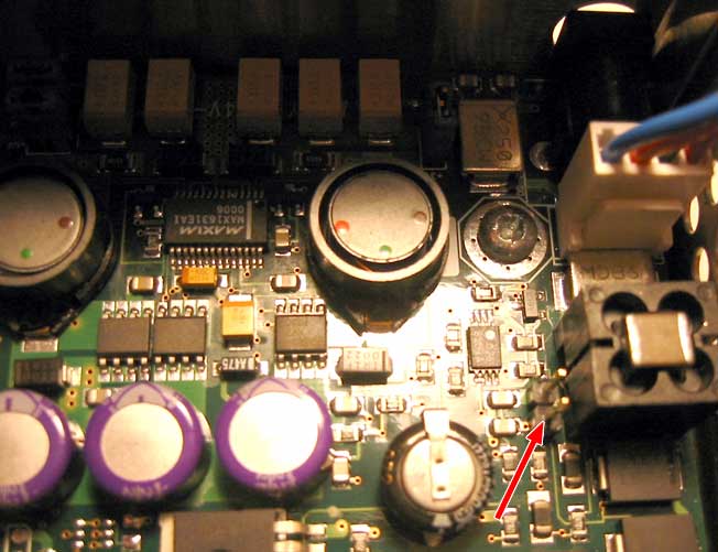
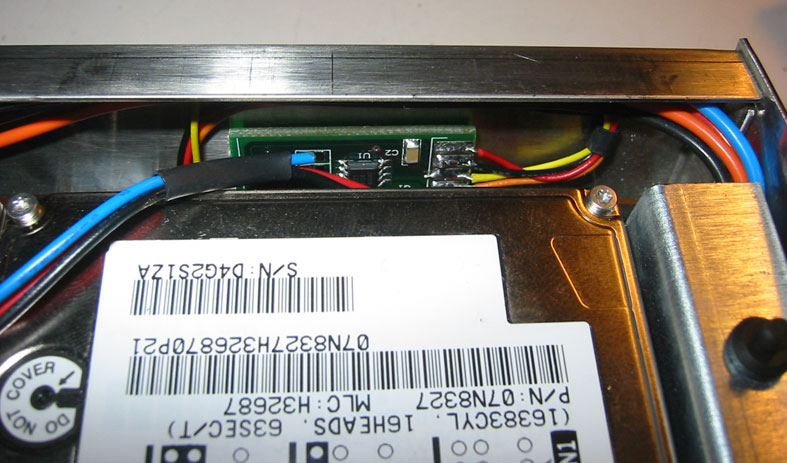
OKAY! So. Let's see if we have this correct:
(+) FAN - to fan positive wire
(-) FAN - to fan negative wire
SDA and SCL:
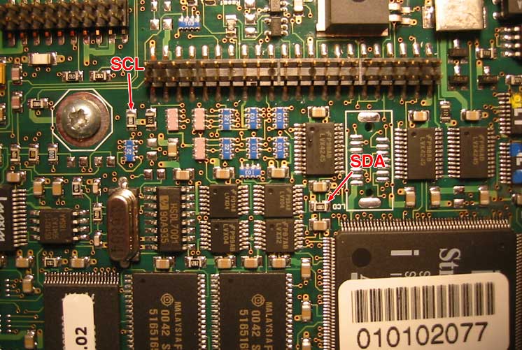
GND - Any Board mounting screw
+12V - One of these pins (which i measured at 11.33V):

All sound good?
Should I jumper A0, A1, and A2 on the controller board or leave them open?
|
|
Top
|
|
|
|
|
#141180 - 09/11/2004 16:41
Re: I2C Fan Controller for Empeg
[Re: loren]
|
carpal tunnel
Registered: 23/08/2000
Posts: 3826
Loc: SLC, UT, USA
|
Sorry for the bump, but could those in the know please confirm all this? I really need to get this in today!
|
|
Top
|
|
|
|
|
#141181 - 09/11/2004 17:24
Re: I2C Fan Controller for Empeg
[Re: loren]
|
carpal tunnel

Registered: 29/08/2000
Posts: 14547
Loc: Canada
|
Top photo looks correct (matches my own photo). Dunno about the bottom photo -- my memory is blank on that.
Cheers
|
|
Top
|
|
|
|
|
#141182 - 09/11/2004 17:29
Re: I2C Fan Controller for Empeg
[Re: loren]
|
carpal tunnel
Registered: 29/08/2000
Posts: 14547
Loc: Canada
|
Quote:
Should I jumper A0, A1, and A2 on the controller board or leave them open?
Leave them open (assuming they float to 0V that way).
|
|
Top
|
|
|
|
|
#141183 - 09/11/2004 18:05
Re: I2C Fan Controller for Empeg
[Re: mlord]
|
enthusiast
Registered: 06/03/2003
Posts: 269
Loc: Wellingborough, UK
|
mlord wrote: Quote:
Top photo looks correct (matches my own photo). Dunno about the bottom photo -- my memory is blank on that.
Loren,
Regarding the bottom photo, it doesn't matter which pin you use they are connected together on the board. It will be easiest to solder the free end of the 12v wire to a jumper then simply plug the jumper into those two pins.
As I indicated in a previous post, I'm not sure whether those pins supply regulated or unregulated 12v. You could try comparing the voltmeter reading here with the voltmeter reading across the outputs of the power supply brick while it is connected to the Empeg. In any case, I'd definately check with Benjammin that his circuit will be happy in the car with the 12v wire connected to these pins, before putting your Empeg back into your car.
|
|
Top
|
|
|
|
|
#141184 - 09/11/2004 18:10
Re: I2C Fan Controller for Empeg
[Re: loren]
|
enthusiast
Registered: 06/03/2003
Posts: 269
Loc: Wellingborough, UK
|
Quote:
Should I jumper A0, A1, and A2 on the controller board or leave them open?
Leave them open. You only need to jumper them if you want to hook up multiple boards to a single Empeg and then you'll also need component RA1 which you probably don't have. I'm not even sure that Hijack knows about boards at other addresses right now so some minor Hijack changes might be needed also.
|
|
Top
|
|
|
|
|
#141185 - 10/11/2004 02:14
Re: I2C Fan Controller for Empeg
[Re: mdavey]
|
carpal tunnel
Registered: 23/08/2000
Posts: 3826
Loc: SLC, UT, USA
|
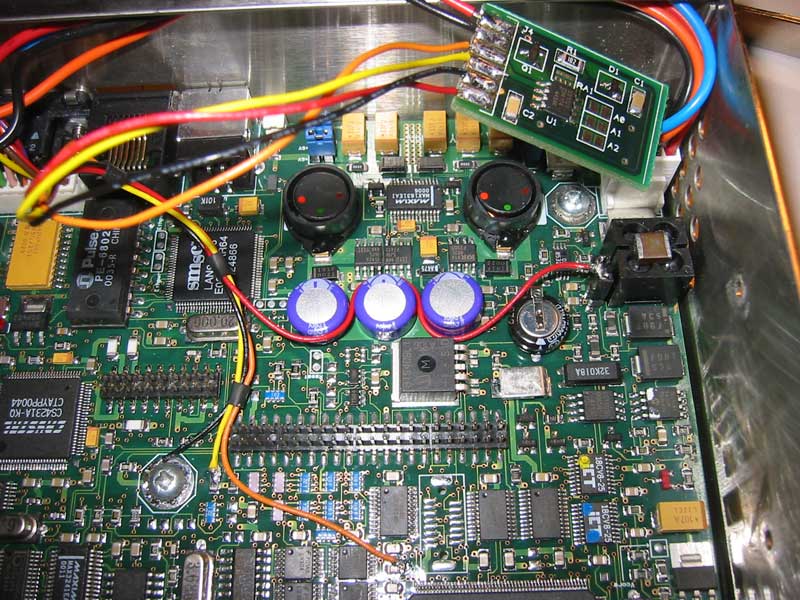
Hooked 'er all up, and it's not working. Argh!
Here's my config.ini where it matters:
[hijack]
khttpd_root_index=/drive0/opt/khttpd/charcoalgray99/index.html
fan_control=1
fan_low=25
fan_high=55
The High Temp Warning is reading:
Curently: +32C/+89F
and my little fan ain't whirling. I'ce checked that I'm getting 12v to the controller board and the wires are where they should be. . . any ideas? Am I not understanding how the hijack settings work? Mark, could you explain them in more detail? Thanks!!!
Attachments
240209-fan_wired.jpg (621 downloads)
Edited by loren (10/11/2004 02:57)
|
|
Top
|
|
|
|
|
#141186 - 10/11/2004 02:55
Re: I2C Fan Controller for Empeg
[Re: loren]
|
carpal tunnel
Registered: 29/08/2000
Posts: 14547
Loc: Canada
|
The Hijack controls are pretty simple and rudimentary -- you've already got them figured out. Here are my notes to myself on this:
Quote:
simply turns it on and sets the high/low thermostat thresholds
from data in config.ini:
[hijack]
fan_control=1 ;; enable control of i2c fan thermostat
fan_low=45 ;; set fan-off threshold (degrees C)
fan_high=48 ;; set fan-on threshold (degrees C)
Note that the I2C thingie has its own thermostat, which may or may not agree with that built-into the empeg.
Try smaller numbers for fan_high.
Cheers
Edited by mlord (10/11/2004 02:56)
|
|
Top
|
|
|
|
|
#141187 - 10/11/2004 02:59
Re: I2C Fan Controller for Empeg
[Re: mlord]
|
carpal tunnel
Registered: 23/08/2000
Posts: 3826
Loc: SLC, UT, USA
|
Ahhh... i didn't have them figured after all. So high is the temp that the fan turns on, and low off. I'd don't know wtf i was thinking it was...heheh. Lemme try that. BRB...
|
|
Top
|
|
|
|
|
#141188 - 10/11/2004 04:32
Re: I2C Fan Controller for Empeg
[Re: loren]
|
carpal tunnel
Registered: 23/08/2000
Posts: 3826
Loc: SLC, UT, USA
|
Sweet. That seems to have worked! That little fan can move some air. I've set it for low=40 high=48, so we'll see how it performs in car. I came up with a pretty clean mounting solution, I'll post pics in a few minutes.
Thanks Mark, Benjamin, and Michael for all your help!
|
|
Top
|
|
|
|
|
#141189 - 10/11/2004 04:40
Re: I2C Fan Controller for Empeg
[Re: loren]
|
journeyman
Registered: 24/04/2002
Posts: 78
|
Hey loren,
Did you get your fan to work?
did you see Benjamin's pictures? it looks like he is using a connector to the pcb board instead of soldering each wire to the board like you did.
How will you mount the board?
How did you solder to the scl and sda on the empeg board? is it okay to just solder at either end of each?
thanks.
|
|
Top
|
|
|
|
|
#141190 - 10/11/2004 04:44
Re: I2C Fan Controller for Empeg
[Re: loren]
|
journeyman
Registered: 24/04/2002
Posts: 78
|
Loren,
Do you think a fan would work in a two drive empeg? I am not sure if the ribbon cable could be routed below the drives (nearer the motherboard) so the fan could blow directly on the drives. If the ribbon cable goes on top of the drives would a fan work?
thanks
|
|
Top
|
|
|
|
|
#141191 - 10/11/2004 04:53
Re: I2C Fan Controller for Empeg
[Re: loren]
|
carpal tunnel
Registered: 23/08/2000
Posts: 3826
Loc: SLC, UT, USA
|
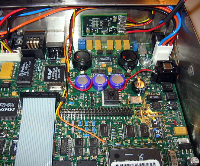
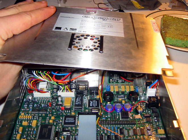
Here's a shot of the wiring layout and where I mounted the board. I used some 3M double sided tape, the thick stuff.
Attachments
240234-fan_controller_mount.jpg (727 downloads)
|
|
Top
|
|
|
|
|
#141192 - 10/11/2004 04:54
Re: I2C Fan Controller for Empeg
[Re: loren]
|
carpal tunnel
Registered: 23/08/2000
Posts: 3826
Loc: SLC, UT, USA
|
Here is a close up of the controller mounted with the drives installed.
Attachments
240235-fan_controller_mount_close.jpg (730 downloads)
|
|
Top
|
|
|
|
|
#141193 - 10/11/2004 04:55
Re: I2C Fan Controller for Empeg
[Re: loren]
|
carpal tunnel
Registered: 23/08/2000
Posts: 3826
Loc: SLC, UT, USA
|
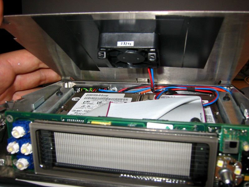
Here's a shot of how I mounted the fan from the bottom. I used two zip ties.
Attachments
240236-fan_mount_bottom.jpg (802 downloads)
|
|
Top
|
|
|
|
|
#141194 - 10/11/2004 04:56
Re: I2C Fan Controller for Empeg
[Re: loren]
|
carpal tunnel
Registered: 23/08/2000
Posts: 3826
Loc: SLC, UT, USA
|
And finally here's a shot of the mount from the top of the lid. Mounted from front to back so the zip ties don't catch when removing from the sled, and they are pretty thin so it shouldn't be a problem. I have yet to try it in car, but it works well in my mlord dock.
Attachments
240237-fan_mount_top.jpg (485 downloads)
|
|
Top
|
|
|
|
|
#141195 - 10/11/2004 05:13
Re: I2C Fan Controller for Empeg
[Re: woops]
|
carpal tunnel
Registered: 23/08/2000
Posts: 3826
Loc: SLC, UT, USA
|
Quote:
Did you get your fan to work?
Yeap. Looks that way so far =]
Quote:
did you see Benjamin's pictures? it looks like he is using a connector to the pcb board instead of soldering each wire to the board like you did.
I think that photo is of a prototype board. It doesn't look like the final board you can see in my photos.
Quote:
How will you mount the board?
3M double sided tap to the back of the case.
Quote:
How did you solder to the scl and sda on the empeg board? is it okay to just solder at either end of each?
I just added a bit of solder to the resistors on the board, then reheated it with the iron and attached the wire.
Quote:
If the ribbon cable goes on top of the drives would a fan work?
Yeap. It works fine in a two drive empeg with the cable on top. That's what mine is. Oh, and you don't want the fan blowing ON the drives, you want it sucking the hot air OUT of the case. At least that's how it's done on almost all computers I've ever seen. =]
|
|
Top
|
|
|
|
|
#141196 - 10/11/2004 07:21
Re: I2C Fan Controller for Empeg
[Re: loren]
|
enthusiast
Registered: 06/03/2003
Posts: 269
Loc: Wellingborough, UK
|
Hey Loren,
Nice install. You made a good job of routing those wires!
In your opinion, where else would work well as a mounting location for the controller board?
|
|
Top
|
|
|
|
|
#141197 - 10/11/2004 11:49
Re: I2C Fan Controller for Empeg
[Re: loren]
|
journeyman
Registered: 24/04/2002
Posts: 78
|
Loren,
Thanks for the photos, documentation, and showing the way!
Please clarify 2 things:
You said:
"I just added a bit of solder to the resistors on the board, then reheated it with the iron and attached the wire. "
Does that mean you attached the wire to ONE END of each resistor? I ASSUME it didn't matter which end?
It looks like you put a jumper on the header and soldered to both prongs, is that correct?
Thanks.
|
|
Top
|
|
|
|
|
#141198 - 10/11/2004 14:31
Re: I2C Fan Controller for Empeg
[Re: woops]
|
Carpal Tunnel

Registered: 08/02/2002
Posts: 3411
|
Attach to the end of the resistor that the arrow points to.
_________________________
Mk2a 60GB Blue. Serial 030102962
sig.mp3: File Format not Valid.
|
|
Top
|
|
|
|
|
#141199 - 10/11/2004 14:48
Re: I2C Fan Controller for Empeg
[Re: loren]
|
carpal tunnel
Registered: 29/08/2000
Posts: 14547
Loc: Canada
|
I would consider adding some hot melt glue blobs to stick down the new wires near where each connects to the empeg main board. That way, the wires won't vibrate off of their solder joints quite so quickly.
Cheers
|
|
Top
|
|
|
|
|
#141200 - 10/11/2004 15:00
Re: I2C Fan Controller for Empeg
[Re: woops]
|
enthusiast
Registered: 06/03/2003
Posts: 269
Loc: Wellingborough, UK
|
Quote:
Does that mean you attached the wire to ONE END of each resistor?
Yes
Quote:
I ASSUME it didn't matter which end?
You assume wrong. Loren was very careful to superimpose arrows on the photo to indicate which end of each resistor the appropriate wire should be soldered. Take another look 
Quote:
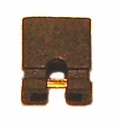
It looks like you put a jumper on the header and soldered to both prongs, is that correct?
The attached photo shows a close-up of how most jumpers appear. That little copper bridge connects the left-hand pin to the right-hand pin. Apply a little solder to the bridge and make a tiny J loop with the wire. Hook the wire under the bridge then heat bridge and wire together. When hot, apply a little solder to "glue" the wire to the bridge. Don't keep the soldering iron on it too long as the plastic insulation on the jumper and/or wire will begin to melt. It helps to use a soldering iron with a fine tip.
Once cool, you could slide a little heat-shrink sleeving over the jumper if you like and then use a hot air gun (paint stripper gun) or hair dryer to shrink the sleeving. Take sensible precautions to protect your fingers and work area from heat damage!
Once done, you can simply plug the jumper onto both the pins on the mainboard.
Edited by mdavey (10/11/2004 15:10)
|
|
Top
|
|
|
|
|
#141201 - 10/11/2004 16:10
Re: I2C Fan Controller for Empeg
[Re: mdavey]
|
carpal tunnel
Registered: 23/08/2000
Posts: 3826
Loc: SLC, UT, USA
|
Quote:
In your opinion, where else would work well as a mounting location for the controller board?
Hrm... That's definitely the cleanest mounting spot I could find. If you have the digital outs punched there, that obviously wouldn't work though. You could lay it any number of places on top of the main board secured with some hot melt glue, towards the back might be better as you have more clearance from the drive tray. The controller doesn't have any contacts on the bottom so it shouldn't be a problem.
All the other questions were answered... thanks guys!
|
|
Top
|
|
|
|
|
#141202 - 10/11/2004 16:21
Re: I2C Fan Controller for Empeg
[Re: loren]
|
journeyman
Registered: 24/04/2002
Posts: 78
|
Loren,
You've made it crystal clear!
Thanks again....
|
|
Top
|
|
|
|
|
#141203 - 11/11/2004 04:11
Re: I2C Fan Controller for Empeg
[Re: mlord]
|
member

Registered: 11/08/2002
Posts: 189
Loc: Champaign, IL
|
Well, they don't "float" to 0V, but yes, they are grounded by default... and leave them that way - they set the address of the DS1721 on the I2C bus... and Mark (Lord) wrote the support for that ID on the bus.
Sorry I haven't been watching the list so closely... I've been swamped at work (another 13 day.. yay)...
Nice pics, Loren, I know I need to update mine... in fact, I'm gonna do that now...
One of these days when I have a minute, I'm going to rip out my old fan controller and put in a new one...
Thanks to everyone else for helping those with questions...
-Ben
|
|
Top
|
|
|
|
|
#141204 - 11/11/2004 04:28
Re: I2C Fan Controller for Empeg
[Re: mdavey]
|
member
Registered: 11/08/2002
Posts: 189
Loc: Champaign, IL
|
There's 2 pads off in the back corner I used for +12 and GND... they are next to the coax power plug...
I need to check again which one was which, but I just hit them up with a VOM and went on autopilot installing it...
-Ben
|
|
Top
|
|
|
|
|
#141205 - 11/11/2004 04:35
Re: I2C Fan Controller for Empeg
[Re: mdavey]
|
member
Registered: 11/08/2002
Posts: 189
Loc: Champaign, IL
|
On the topic of 12V vs 5V.....
the fan will definitely put up with 13.8 and even a little more like the car might put out...
The DS1721 has a resistor with a 5.1V zener diode.. so in a sense, it has its own 5v supply.
As I mentioned, I used the +12V pads that are in the back corner next to the coax connector for external power. They're in parallel with the power input from the sled connector. Thus, the fan will operate when plugged into wall or car.
Enjoy.
p.s. my Image editor for windows seems hosed... might if I borrow the one you posted Loren?
|
|
Top
|
|
|
|
#141206 - 11/11/2004 06:30
 Re: I2C Fan Controller for Empeg
[Re: benjammin]
Re: I2C Fan Controller for Empeg
[Re: benjammin]
|
carpal tunnel
Registered: 23/08/2000
Posts: 3826
Loc: SLC, UT, USA
|
Quote:
might if I borrow the one you posted Loren?
By all means, help yourself.
|
|
Top
|
|
|
|
|
#141207 - 23/11/2004 23:47
Re: I2C Fan Controller for Empeg
[Re: loren]
|
member
Registered: 11/08/2002
Posts: 189
Loc: Champaign, IL
|
Quote:
Quote:
Did you get your fan to work?
Yeap. Looks that way so far =]
Quote:
did you see Benjamin's pictures? it looks like he is using a connector to the pcb board instead of soldering each wire to the board like you did.
I think that photo is of a prototype board. It doesn't look like the final board you can see in my photos.
Definitely a "proto" - when I did only one... I just hand wired it. At some point, I'll connect a new one in there to replace the original.
Quote:
Quote:
How will you mount the board?
3M double sided tap to the back of the case.
I used a dab of hot melt.
Quote:
Quote:
How did you solder to the scl and sda on the empeg board? is it okay to just solder at either end of each?
I just added a bit of solder to the resistors on the board, then reheated it with the iron and attached the wire.
That's how to do it.. use a LOW WATTAGE IRON. And be quick with the connections. Use enough heat, but I don't stick around more than 3 seconds or so...
|
|
Top
|
|
|
|
|
|

 Previous Topic
 Index
Index