Unoffical empeg BBS

Quick Links: Empeg FAQ | RioCar.Org | Hijack | BigDisk Builder | jEmplode | emphatic
Repairs: Repairs

Topic Options
#359643 - 09/09/2013 00:45 Display Board Technical Drawings?
Joe Gorman
new poster

Registered: 04/09/2002
Posts: 20
Loc: Oak Hill, WV, USA
I'm making a custom faceplate out of acrylic for my empeg to make it look like a classic radio for my Datsun 510 (bakelite knobs with chrome inlays, etc)

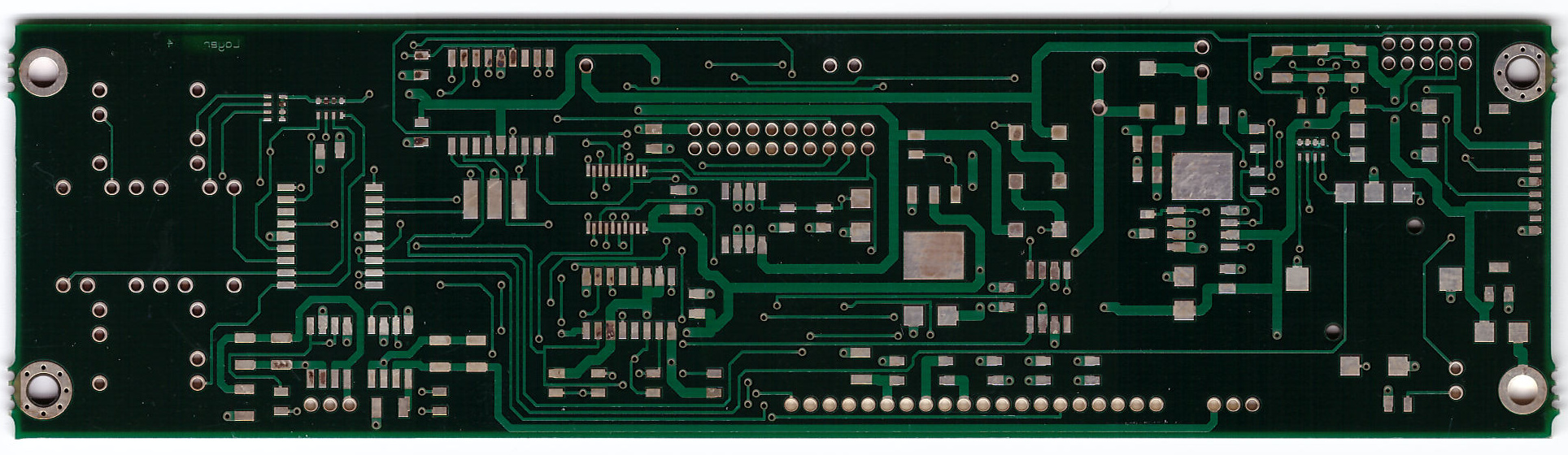
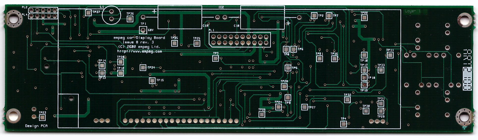
In order to get the design right, I need accurate (better than I can get with a camera) locations of the screw holes, two-function button/knob, screen, and IR sensor.

Does anyone have either technical drawings of the display board, or know where I can get them? I have AutoCad, Sketchup, GIMP, and Adobe software.

-joe


Attachments
68 radio.JPG

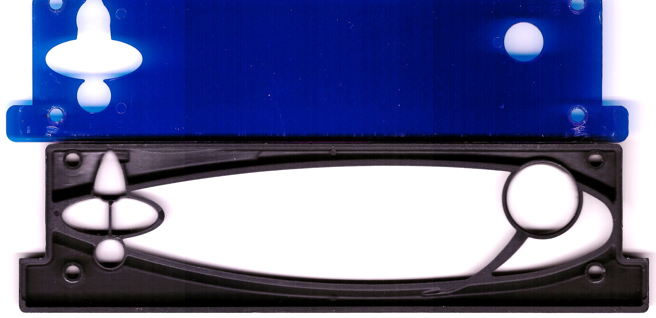
Description: Inspiration


Top
#359646 - 09/09/2013 11:16 Re: Display Board Technical Drawings? [Re: Joe Gorman]
mlord
carpal tunnel

Registered: 29/08/2000
Posts: 14472
Loc: Canada
Originally Posted By: Joe Gorman
Does anyone have either technical drawings of the display board, or know where I can get them?


These may provide a decent starting point.
The scans were done at 300x300dpi, so each pixel in the images represents exactly 1/300th of an inch.

(Edit: fixed orientation and naming of original uploads)


Attachments
empeg_display_FRONT.jpg (268 downloads)
Description: Front of empeg Mk2 display board.

empeg_display_REAR.jpg (250 downloads)
Description: Rear of empeg Mk2 display board.


Top
#359648 - 09/09/2013 15:16 Re: Display Board Technical Drawings? [Re: mlord]
tfabris
carpal tunnel

Registered: 20/12/1999
Posts: 31563
Loc: Seattle, WA
One could also try scanning the backside of the fascia on a flatbed scanner, in the same fashion.
_________________________
Tony Fabris

Top
#359651 - 09/09/2013 17:56 Re: Display Board Technical Drawings? [Re: tfabris]
mtempsch
pooh-bah

Registered: 02/06/2000
Posts: 1996
Loc: Gothenburg, Sweden
Originally Posted By: tfabris
One could also try scanning the backside of the fascia on a flatbed scanner, in the same fashion.


I'm fairly sure there should be pictures of that around somewhere from back when 303, IIRC, did the aluminum fascias and knobs. Haven't been able to find them (but haven't been digging very hard or long)
_________________________
/Michael

Top
#359653 - 09/09/2013 20:38 Re: Display Board Technical Drawings? [Re: tfabris]
mlord
carpal tunnel

Registered: 29/08/2000
Posts: 14472
Loc: Canada
Originally Posted By: tfabris
One could also try scanning the backside of the fascia on a flatbed scanner, in the same fashion.


Attachments
fascia_backside.jpg (254 downloads)
Description: Backside of fascia, 300x300dpi.


Top
#359679 - 12/09/2013 20:03 Re: Display Board Technical Drawings? [Re: Joe Gorman]
pca
old hand

Registered: 20/07/1999
Posts: 1102
Loc: UK
Attached is a 2D DXF file of the top and bottom layers of the last version of the Mk2A display board. It should be exactly 1 to 1.

pca


Attachments
issue 9R2 empeg display board 2d.dxf (407 downloads)

_________________________
Experience is what you get just after it would have helped...

Top
#359680 - 12/09/2013 20:09 Re: Display Board Technical Drawings? [Re: Joe Gorman]
pca
old hand

Registered: 20/07/1999
Posts: 1102
Loc: UK
Here's one with the silk screens, which will be more useful.

pca


Attachments
issue 9R2 empeg display board 2d with silks.dxf (416 downloads)

_________________________
Experience is what you get just after it would have helped...

Top