Registered: 06/03/2003
Posts: 269
Loc: Wellingborough, UK
Quote: Does that mean you attached the wire to ONE END of each resistor?
Yes
Quote: I ASSUME it didn't matter which end?
You assume wrong. Loren was very careful to superimpose arrows on the photo to indicate which end of each resistor the appropriate wire should be soldered. Take another look
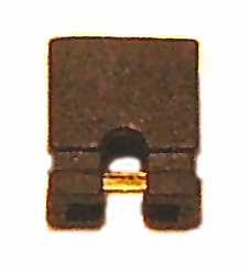
Quote: It looks like you put a jumper on the header and soldered to both prongs, is that correct?
The attached photo shows a close-up of how most jumpers appear. That little copper bridge connects the left-hand pin to the right-hand pin. Apply a little solder to the bridge and make a tiny J loop with the wire. Hook the wire under the bridge then heat bridge and wire together. When hot, apply a little solder to "glue" the wire to the bridge. Don't keep the soldering iron on it too long as the plastic insulation on the jumper and/or wire will begin to melt. It helps to use a soldering iron with a fine tip.
Once cool, you could slide a little heat-shrink sleeving over the jumper if you like and then use a hot air gun (paint stripper gun) or hair dryer to shrink the sleeving. Take sensible precautions to protect your fingers and work area from heat damage!
Once done, you can simply plug the jumper onto both the pins on the mainboard.


 Previous Topic
 Index
Index
